Week 8
Embedded Programming
In this week,the goal is to learn about micro controller using data sheet and program it using different programming techniques.The hello board which already done. Now it need to be programmed to get the output
Attiny44 Data sheet.
The pin out diagram for the controller used is the above. 14 pins.
I downloaded the datasheet from here
It contains a lot of informations.Pin configuration etc. i went through required details.
Programming or burning a micro controller:
Programming or burning a microcontroller means to transfer the program from the compiler to the memory of the microcontroller.A compiler is the software which we can use to write, test and a program for our controller.
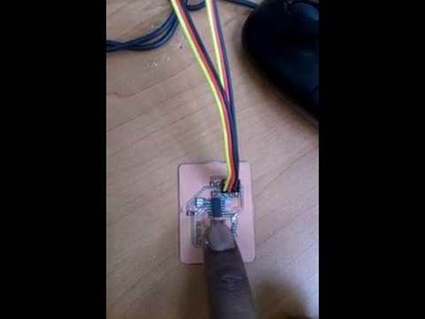
For programming we need a programmer hardware. I used USB programmer.
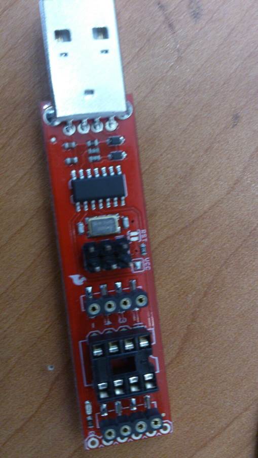
Before programming, i checked the board well whether there is any short circuit contacts with the multimeter.
I checked the VCC and RESET pin connection to the ISP pin header. Verified that my board pins of VCC and RESET matches the programmer.
Using the below pinout, i verified it.
Programming software(compiler)
For programming, I used the Arduino IDE(Arduino Website).
I downloaded the AT tiny library and included in the board manager of arduino.
For that i followed the steps given in this Website
I downloaded the arduino software. After that for configuring the board. Since the board used is AT tiny,In arduino IDE,
Tools -->Board -->ATtiny
Tools → Processor -->ATtiny44
Tools → Clock -->20mhz(external)
Tools -- >Programmer-->USBtinyISP
Burning the bootloader:
Before uploading program, I have to burn bootloader. For that
Tools -->Burn Bootloader
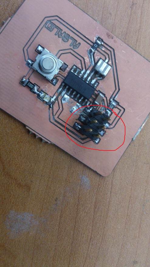
When i burn the bootloader, There is error. It’s showing rc=-1 and to check the connections.
I checked the connection traces and soldering of the board. There was a less soldering in a controller pin and it was not connected properly.
I corrected it and tried again..
Now the bootloader is burned.
Output
After bootloader is burned,i made changes in the code available in arduino examples and configured the LED and button pins.
I referred the Attiny pin configuration and corresponding pin is changed in the program.
LED and button pins are no.5 and 8 respectively.
Then i downloaded the program.downloading was successful.
But LED was not glowing.
So i checked the led with multimeter after removing. It was not working.
I removed the solder and then soldered a new LED .
After that i got the output.
Video link for the output is below
I downloaded a blink program for LED too and it was also working.
Files:
LED with Button program in arduino IDE: Arduino Code
Blink program in Arduino IDE: Button code